SDR links |  |
I/Q In phase / Quadrature
Detector By Dan Tayloe (N7VE)
Tayloe detector & mixer
IQSD
PC-based SDR - 1
PC-based SDR - 2
PC-based SDR - 3
PC-based SDR - 4
Quadrature Signals
Digital Solutions
Debugging the RS232 serial port
Step 7 : Tayloe Detector Optimisation
The K3 version at 8.215 MHz need 320 KHz bandwidth ( 4% of Fc )
to be compatible with Power SDR which need 2x 160 KHz.
Due to his capacitors c39, c11, c31, c18, 10 nF,
and Z in 12.5 Ohms due to T4 ratio 4/1,
so, BW = 1.27 MHz & Q = 6.5
I am only interested by a compatibility with CW-skimmer
which monitor 2x 11.4 KHz.
The minimum bandwidth assuming offset at 5800 HZ is
2x ( 11.4 + 5.8 ) = 17.2 KHz ( 3.8% of 455 KHz )
Less than 5% is a correct figure.
With capacitors value at 220 nF
BW = 58 KHz & Q = 7.9
For those who want large BW compatible with power SDR,
they must build the IF out on 1st IF at 47.21 MHz.
LP-pan hardware, IC's & transformers, are compatible,
but oscillator, filters and detector have to be matched for this frequency.
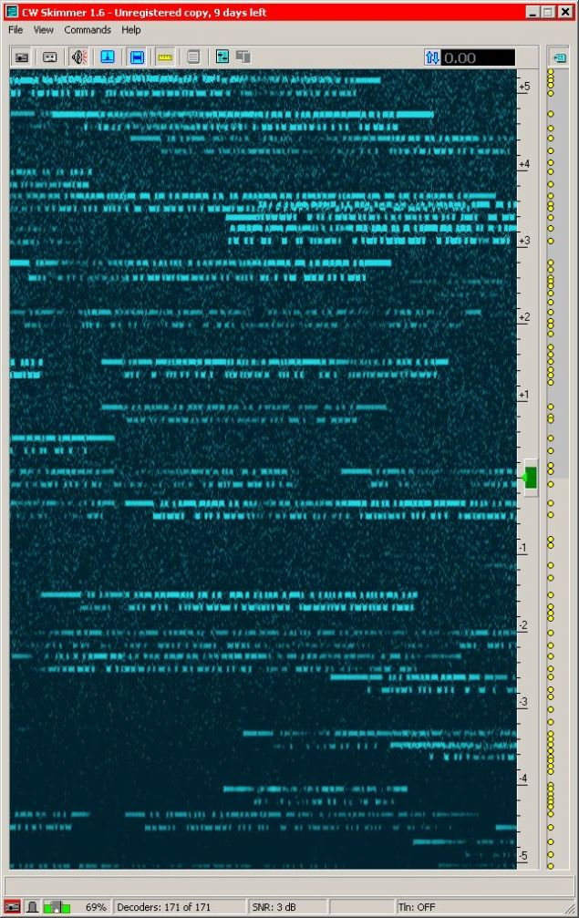
Sample of screen copy,
NAQP rtty feb26 2011
1830z 14086MHz
Click on to enlarge
NAQP rtty feb26 2011
1830z 14086MHz
Click on to enlarge
But if you realy want a customized xtal, Delcom in Belgium about 20 € or 27 $
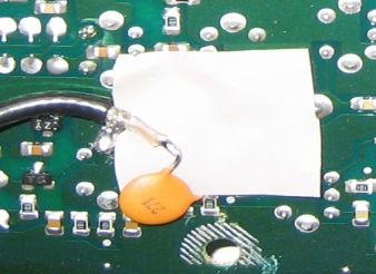
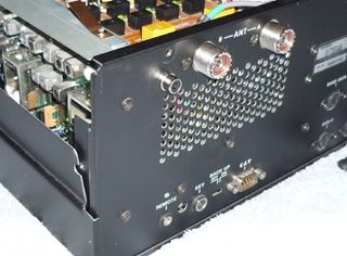
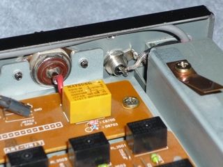
Connector installation
Remove temporarly antenna coupler, or tilt it over the PA.
Use tape to secure space around drilling area, and have vaccum cleaner ready.
There is just enough space for a Cinch or BNC connector
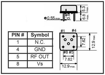
4
1
5
8
out
v+ gnd
1
5
8
out
v+ gnd
IF
out
out
Rx2
fan
<--
Step 6 : Gain adjustment U5
U5 gain isolator amp can be adjusted using R29.
Measured BNC to J4, loaded by 50 ohm of the test equipment,
not 200 as in normal use.
On SN 1032, K3 8.215 MHz classic version,
- min gain, R29 fully CW is about 15dB
- max gain, R29 fully CCW is about 25dB.
This is for the full chain,
including preamp (12-14dB ) with attenuator Off,
& filters tuned, ( C34 C35 ) for minimum loss .
In same conditions, but this chain has NO preamp,
on SN 1108, 455 KHz home made customised version,
- min gain, R29 fully CCW is about -3 dB
- max gain, R29 fully CW is about +13 dB,
and gain increase in reverse side... there is a problem.
Gain mystery is resolute, R29 track was cut,
so it was a switch, R= infinity or R= zero
when whiper was in contact with other end.
so now, everything is back to normal,
- min gain, R29 fully CW is about +4 dB
- max gain, R29 fully CCW is about +13 dB,
good values for a chain without preamp.
Preventively again, in order to assume frequency divided by near 20,
decouping capacitors, c25 c23 c26 c16 c38 c15, 1µF are now 22µF.

Old school TTL oscillators |  |
74LS132 schematic
74LS00 schematic
74LS00 prototype
-
Only for Home made & recycling
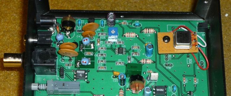
Bottom draw and cabinet overflow...


Input Filter R29 Output Filter J4 output integrated
U5 for test oscillator
U5 for test oscillator


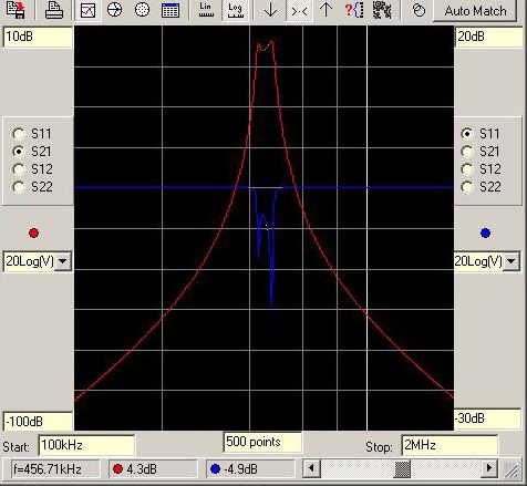
Due to component tolerance,
it is necessary to tune
isolator amp and its filters
with a MiniVNA or equivalent,
I use HP 141T spectrum analyzer
+ HP 8443A the matched tracking generator.
Isolator amp output is available via J4.
Remove jumper between pin 2 -3,
set an output cable, pin 1 gnd, pin 2 signal.
Depending on component tolerance
100 pF can be out of tuning range,
so changing fixe capacitor must be done.
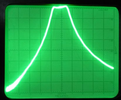
Final tuning is shown at right -->
H= 50 kHz / div
V= 10 dB / div
it is necessary to tune
isolator amp and its filters
with a MiniVNA or equivalent,
I use HP 141T spectrum analyzer
+ HP 8443A the matched tracking generator.
Isolator amp output is available via J4.
Remove jumper between pin 2 -3,
set an output cable, pin 1 gnd, pin 2 signal.
Depending on component tolerance
100 pF can be out of tuning range,
so changing fixe capacitor must be done.
Final tuning is shown at right -->
H= 50 kHz / div
V= 10 dB / div
200 300 400 455 500 600 700
Last E is optional


Update 21/09/2011

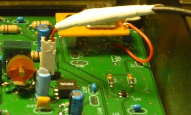
Step 1 : IF out
Everybody knows there is no IF out on FT-1K, so i had to build it.
I found solution on DH1TW web site, Tobias did it.
It is easy to make, all details are here : 2nd IF 455 kHz out
Gain measured between antenna input and IF output is 10 dB. ( No AGC in this area )
By the way, the IF width is +-20 KHz, at 2nd mixer output, ( before narrow filters )
BW is given by 47.21 MHz 1st IF filter .
Gain is mostly made by 47 MHz amp Q8024.
IF signal capture for same level is easier at 455 KHz than 47.21MHz
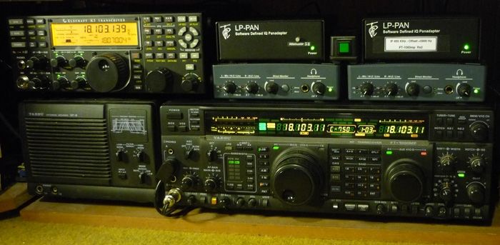
Shack Conflict
The FT-1000mp was jealous of the K3 because this one had a LP-pan.
Operator was watching split area on K3 on one side,
and tuning FT-1k on the other, it was not an efficient operating way.
So after a few months, when it was clear,
LP-pan was a remarkable IQ panadapter,
so I decided to buy another one in order to shift it to 455 KHz,
the 2nd IF of FT-1000mp 2nd Rx.
The LP-pan has no hardware compromise,
this is why it reaches near theorical IQ limits,
when environnement, including cables, did not degrade it.
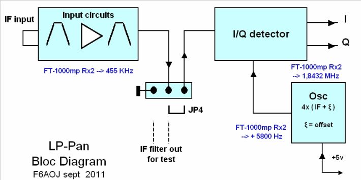
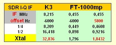
Step 2 : Oscillator design
Oscillator frequency runs at 4 times IF plus or minus an offset of some KHz
K3 IF is 8.215 KHz and selected offset is - 6000Hz
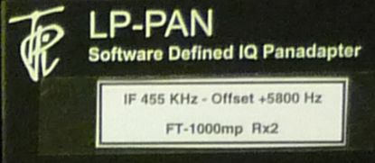
Direct shift to 455 KHz & - 6000Hz gives 1.796 MHz xtal frequency, which is not standard.
But with the offset at "plus 5800", frequency becomes 1.8432 MHz,
which is a standard value used by Baud rate generators clocks.
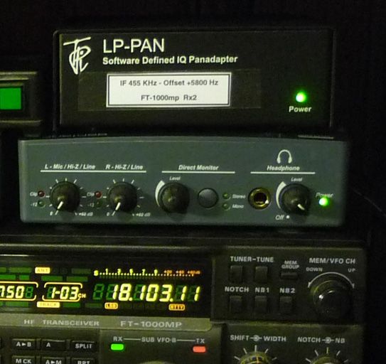
Step 4 : Power up
At this stage LP-pan 455
can power up.
Start USB sound module,
I use Creative EMU-02-02.
Launch CWskimmer
Use following parameters :
Radio
- Hardware Type : SoftRock IF
- Sampling Rate: 192 KHz
- Pitch for CW : personal value
for RTTY : 1000 Hz
( this will be explained below )
- Audio IF, the offset value : +5800 Hz
and It is finished.
So now, on FT-1000mp
set "Dual Rx" ON
and then when turning B vfo,
we can see spectrum rolling
up or down on screen.
Transmit frequency is as usual
right in front of green arrow.
Here we are !
Step 3
Filters & board assembly
Filters & board assembly
The input isolator amp U5 has one filter on each side.
In the FT-1k case, IF signal is just going out from a serious filter,
so, in a first approach, you can bypass them using two straps.
As for the oscillator don't install filter components on PCB
and remove some CMS coils.
Input side : L10 L8 L9 C21 C13 C34 C28
output side : L4 C12 C35
Put a strap between L9 and L10 hot side
Put a strap between L4 ( R8 side ) and C12 ( J4 pin 2 side )
Due to Frequency nearly twenty times lower,
decoupling capacitor 10 nF ( 103 ) has been replaced by 100nF ( 104 ).
All other components must be assembled as indicated in manual.
8.2 LP-pan Power Cable
In order to reduce common mode injection,
it is better to use +12v available on rear panel of the radio
8.3 EMU-0202 to PC link
In order to optimise data transfer with PC don't use external USB Hub port,
internal ports or port on PCI board give much better transfer rate.
CWskimmer display number of decoders open.
This value depends on pileup size and tranfer rate,
this is a perfect tool to find the fastest USB port on your PC.
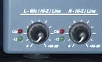
8.4 EMU-0202 Controls
In order to help CW-skimmer Gain/Phase corrector to do the best
keep EMU-02-02 input Right & Left level controls in same position at any time,
Because led monitoring sytem is only compatible with voice,
Most part of the time front panel green leds are Off,
when flashing, reduce gain.
When monitoring empty band, it seems to me, gain can be rised up
until the trace at minus offset from green arrow, ( offset value including sign )
disappear in the screen noise, green leds always Off.
The zero beat line is visible at -5800Hz on 455 unit, ( and +6000 on K3 standard version )
so it does not appear in pileups running up 5 to 10 KHz.
8.5 Final setup
Stacking equipments generate a thermal problem,
a small 80mm square fan was added right of 455 pack to void calorie accumulation.
Step 9 : Background
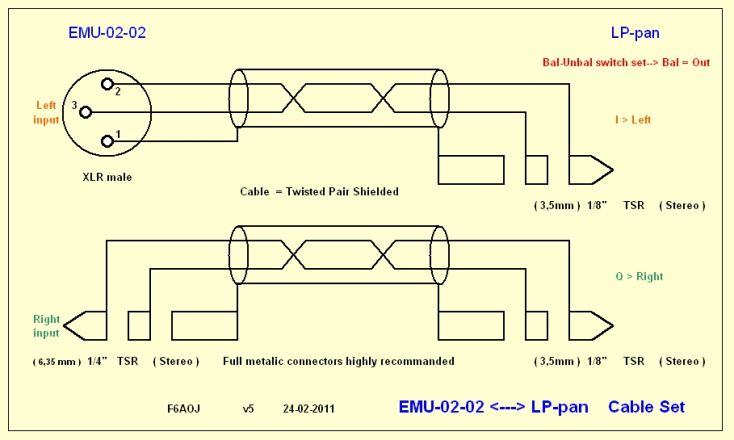
9.1 LP-pan <--> EMU-02-02 cable set
9.1 LP-pan <--> EMU-02-02 cable set
Signal coming out of LP-pan is extremely sensitive,
any noise injected in the link with EMU-02-02
will reduce number of valid bits processed.
Cable set length must be as short as possible,
less than one foot.
Full metalic connectors are highly recommanded,
and twisted pair shielded must be used,
in a balanced configuration.
Unbalanced mode is just good for maintenance operation.
LP-pan stacked over the EMU permit short cables,
and it makes IF cable short too
with stacked box above the radio.
EMU Input level controls are part of the major station commands,
so they must be near operator hands.
For those reasons stacking, radio, EMU and LP-pan is a natural way.
Underground LP-pan 455 v3.1
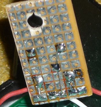
Step 2b : Oscillator construction
Preliminary :
Don't install components of the original oscillator
when assembling your LP-pan in kit form.
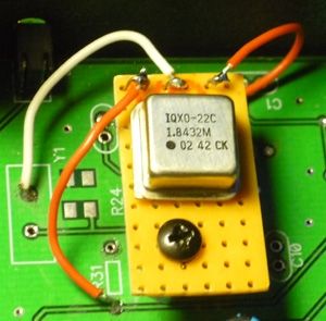
Y1 Q1 R10 R24 R25 C10 C30 R26 C1 C33 ( schematic )
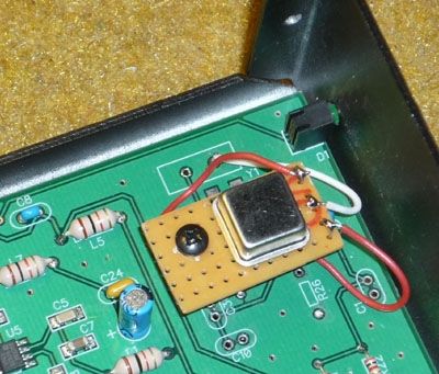
This will save a track cut on PCB,
DC power and undesired signal at 32.836 MHz.
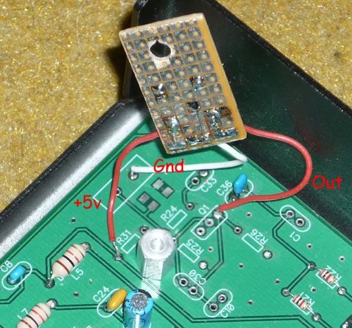
The final version of the oscillator uses a 5v integrated chip
at 2 € ( less than 3 $ )
It is installed at the same place as Preamp,
which is not necessary in this project,
RF head of 2nd Rx has the same gain
as the optional preamp.
last Update sept 21 - 2011
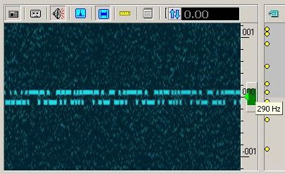
MMTTY screen capture
Resulting spectrum displayed by MMTTY
with RX on dummy load.
Major MMTTY setup
- Mark : 915
- Polarity : Reverse
- Squelch : OFF
- ATC : ON
- AFC : OFF
AFC is OFF in order to be strictly zero beat
when transmiting in FSK
( or DFSK versus AFSK in Elecraft dialect )
USB sound dongle
Output signal coming from EMU-02-02
is too high for dongle mic input,
an 1/10 attenuator is necessary.
A basic voltage divider with 2.2k & 220 ohm is perfect.
Most of sound dongles have now an integrated AGC,
they are compatible with voice, not with CW or RTTY.
So they must be set OFF using advanced parameters
availables in audio mixer slice, option "Record"
Set input level at about 50%.
Don't put dongle directly in PC USB plug,
use an extention cable,
and make Mic cable as short as possible,
in order to keep audio signal as clean as possible.
Dongle clock is not so accurate than EMU,
so adjust using MMTTY setup, in order to have ellipses
exactly in same shape in different MMTTY windows.
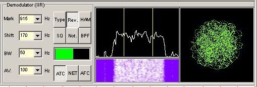
CWskimmer screen capture
CWskimmer monitored channel bandpass
must be adjusted at 290 Hz minimum,
with mouse roller,
below it is hazardous.
- Note: Green arrow is exactly between Mark and Space,
to match MMTTY requirements
- Remind : Pitch must be tuned at 1000 Hz
- Commands : set Blind mode to ON,
because RTTY code is not supported,
in return this save a lot of PC resources.
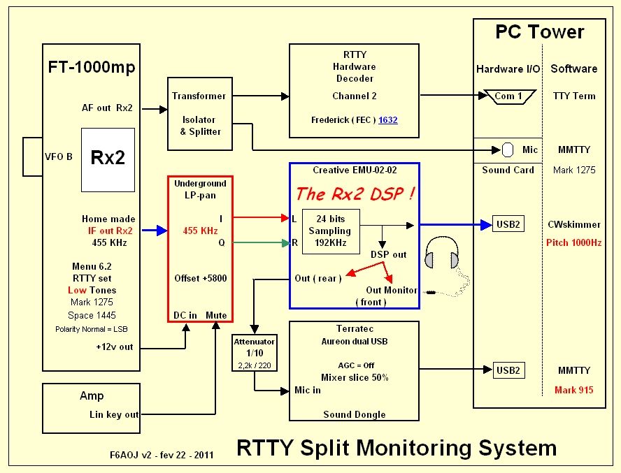
Step 8 : RTTY monitoring
Dramaticaly pitch value managed by CWskimmer is 1000Hz max.
So monitoring RTTY with the center frequency right in front of the green arrow,
is acrobatic...
And this is only possible if "Low Tones" are in use in FT-1k menu ( 6.2 )
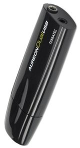
In order to decode RTTY with Rx2,
because CWskimmer decodes only CW,
inject EMU-02-02 channel out,
into an USB sound dongle,
I use Terratec Aureon Dual USB,
and decode with something i.e. MMTTY.
In this case set Mark at 915 Hz ( the lowest value )
915 + (170/2 ) =1000 supplied by highest pitch value of CWskimmer.
Set Reverse ON, due to frequency convertion.
The only one solution, but it's works.
RF-space has extended pitch up to high tones
and are very proud to annonce it.
I, and others have asked to MR Skimmer to do the same,
we never got any answer...
Humor
-- I --
-- I --
Again, LP-pan is a remarkable piece of hardware,
and more flexible than expected, as this page prove.
Contrary to SDR let think, the SDR concept fails because of software...
Nothing in open,
i.e.
- Pitch management by CW skimmmer
- LP-bridge is dedicated to K3,
and so on.
If i am wrong let me know, it will help me.
Software Defined Radio,
supposes raffined software,
in reality software is eccentric.
This is why this project doesn't use software,
except CWskimmer, by default and not by pleasure.
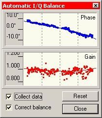
The core is remarkable,
especially the phase gain corrector, ( I/Q balance --> )
but user interface is extremly limited.
This generates more than a disappointement.
Most SDR software are pure show room demonstrators
without connection to DXers needs,
Power SDR is typical.
Extra software as RigSync dont change anything,
after clik for QSY on VFO B, VFO A finishes in reverse...
Before I got LP-pan, during ten years,
I was using Digipan as narrow band spectrum monitor,
it was a big help, like when a blind recovers one eye,
and during the last decade, I made thousands of DX under its indications,
but now,I think, it was just a magnifyng glass, versus LP-pan telescope.
-- II --
Peace is back in the shack,
the FT-1000mp doesn't complain any more, and K3 doesn't parade all the time,
and the operator is cool, monitoring DXers jaming in split area.
FT-1000mp is back after a 250$ lifting, only !
Add about 130$ for the EMU-0202, which is also the new Rx2 DSP !
This impact the difference between Rx1 & Rx2, it's disapeared.
So It can compete now and for years
with many recent transceivers including K3.
I own one and can talk about it, but it is another purpose.
Since the lifting, FT-1000mp is looking at the californian youngster from the top.
An IF-2000 board cost 190$ just for a 80 MHz to 10 MHz converter
without panadaper, where is the progress ?
It is much less than 800$ for the stupid Yaesu DMU-2000 for sure.
It would have been a bad idea to change for a FT-2000.
Worse it is, the SM-5000, a pure gadget at 500$.
-- III --
Eyes on screen and hand on VFO B,
is finaly my way, with reliable existing tools.
On the desk the mouse is laughting,
it considers this control loop as antique,
but it is the best I never had, very reliable, doing exacly what any DXer needs,
and free of software constraints and software bugs.
I am only Jeff, not Martin, so let me dream just a second,
In some decades or when hens will have teeth,
SDR will become DSR, Delicate Software Radio.
For now it is still SDR, Software Definitly Rugged...
Jeff F6AOJ since 1969
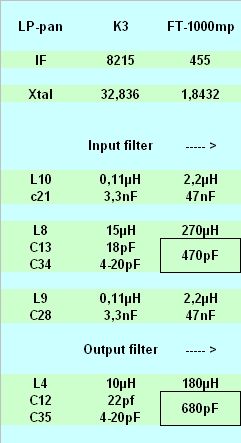
Step 5 : Filters Modifications
For those who will use the LP-pan 455 on a wide band IF out,
it is usefull to have full spec filters.
Input filter is a band pass, it uses
two LC Parallele, separated by one LC serie,
a very conventional structure.
Output filter is also a band pass, but a unic LC serie.
RFsim99 was used to recalculate values for 455 KHz
and L/C ratio is respected in order to keep form factor.
Adjustable components, variable capacitors are now 100 pF
Components theorical values are given in following chart.
By the way, after check, transformers T3 & T4 are compatible 455 KHz.


RF Tech |  |
RF Tech
Ham Product Review
Ham-nalyse
K3 story
SDR
AO-Journal |  |
Trafic
RF Tech.
Stn F6AOJ
Pixel mania
Ham world
Editor desk
Home |  |
La Une
Sommaire
Updates
Search
SDR |  |
SDR wiring
Splitter 2x Rx
CATastrophe
Route Tard
Digikeyer
CAT converter
Station Master
Stn Master extension
Under Ground LP-pan
LP-pan & FT-1000mp
VFO sync
Twin IF LP-pan
Twin clock
CMOS osc trim
Rx ant in-out box
Rx ant out TS-590
Mauvais plan
Digital Solutions
SDR gallery
SDR jungle @ F6AOJ
Comment ça marche
K3 & SDR File IF
K3 & SDR Software saga
Babel Fish
To Translate this page
To Translate this page


RF Tech |  |
RF Tech
Ham Product Review
Ham-nalyse
K3 story
SDR

AO-Journal |  |
Trafic
RF Tech.
Stn F6AOJ
Pixel mania
Ham world
Editor desk
SDR |  |
SDR wiring
Splitter 2x Rx
CATastrophe
Route Tard
Digikeyer
CAT converter
Station Master
Stn Master extension
Under Ground LP-pan
LP-pan & FT-1000mp
VFO sync
Twin IF LP-pan
Twin clock
CMOS osc trim
Rx ant in-out box
Rx ant out TS-590
Mauvais plan
Digital Solutions
SDR gallery
SDR jungle @ F6AOJ
Comment ça marche
K3 & SDR File IF
K3 & SDR Software saga
Home |  |
La Une
Sommaire
Updates
Search
Option Zéro Pub : utilisez Firefox le navigateur de Mozilla , et installez l'option Adblock Plus téléchargez le fichier Filtres